


Fountain Inkwell – Patented 1855
| Categories | Mechanical - Pump / Siphon |
| Type | Siphon |
| Material | Cast iron, Glass |
| Markings | See Narrative |
| Manufacturer | Undetermined |
| Origin | United States |
| Date or Era | circa 1855 |
| Measuring | Larger Version: 7” x 6” x 6” high; smaller: 5 ½” x 3 ¼” x 4” high |
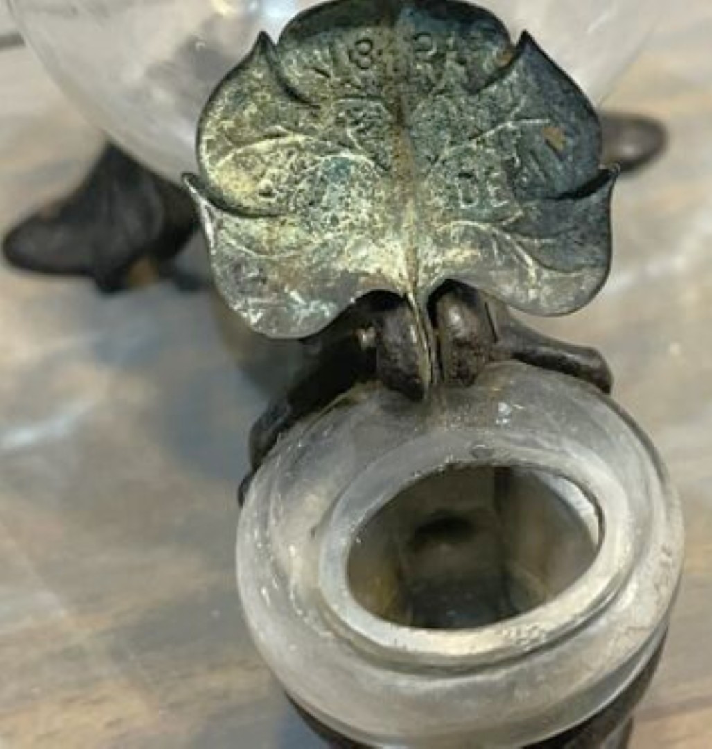
| Patent | Patent No. 13,902 dated December 11, 1855 |
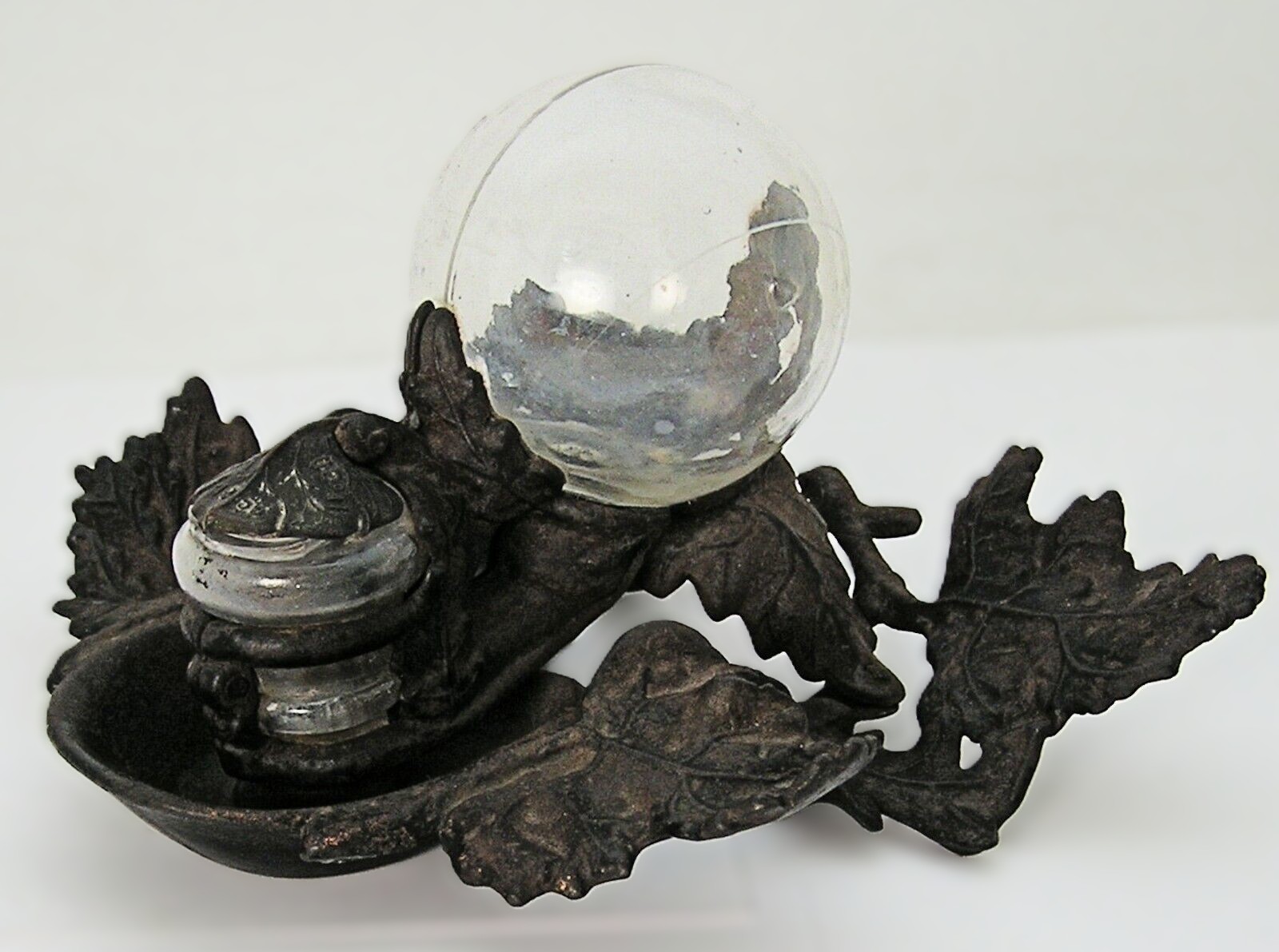
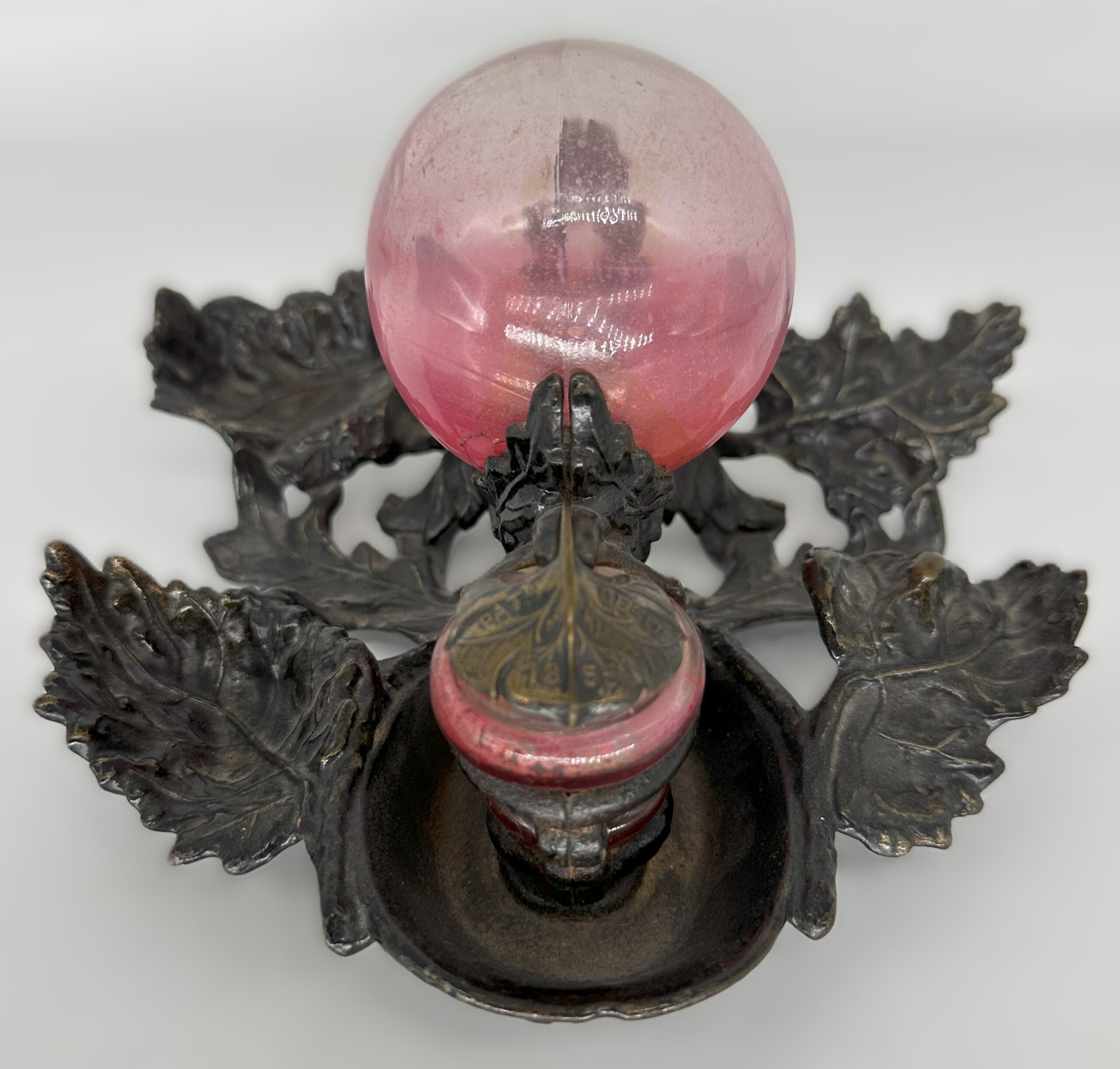
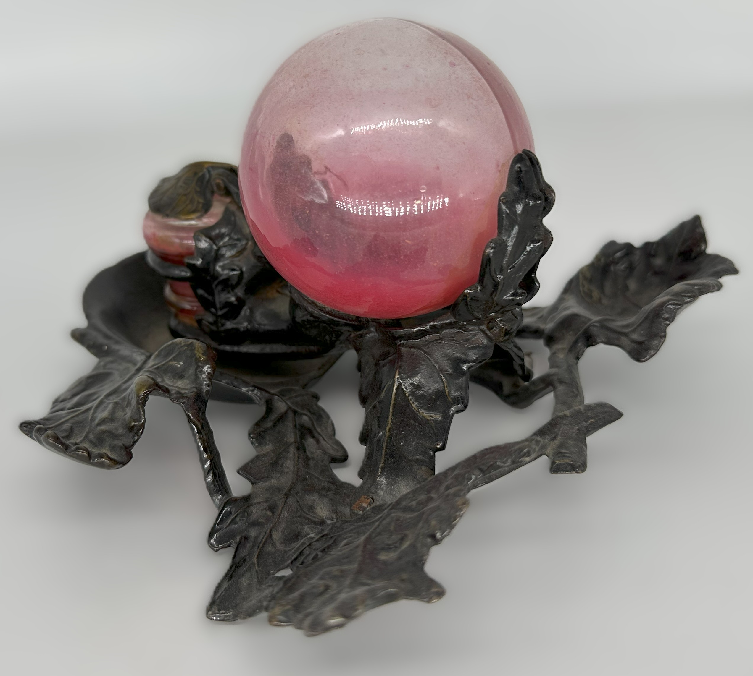
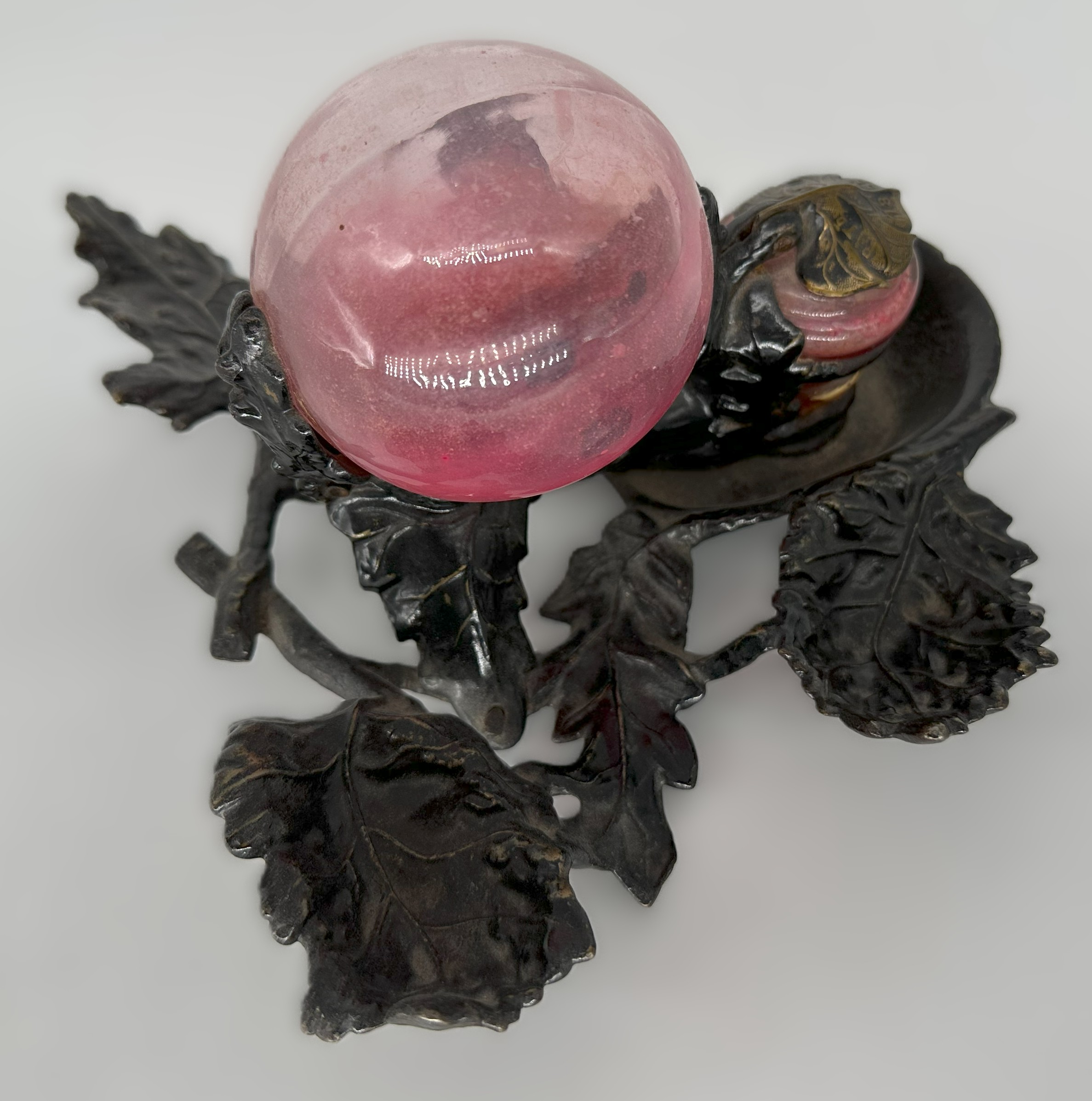
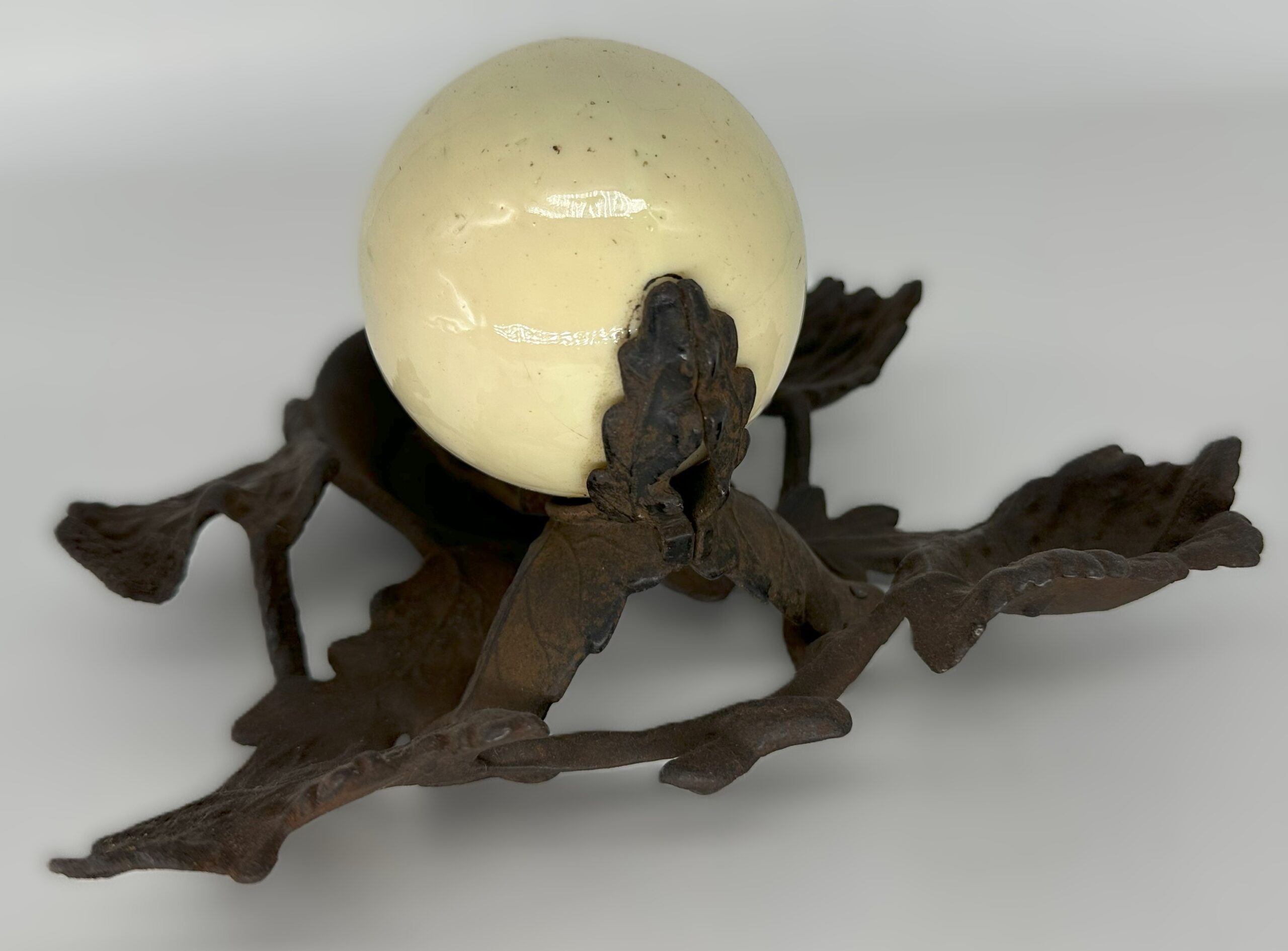
This is an example of an American “fountain” inkwell from the mid-19th century. The piece consists of two primary components: a clear glass inkwell and a heavy cast iron frame. The frame features an ornate, stylized leaf design that gives it a decorative, organic feel, and it has a hinged brass leaf-shaped lid on the front, embossed with the patent date: PATD. DEC. 11, 1855.
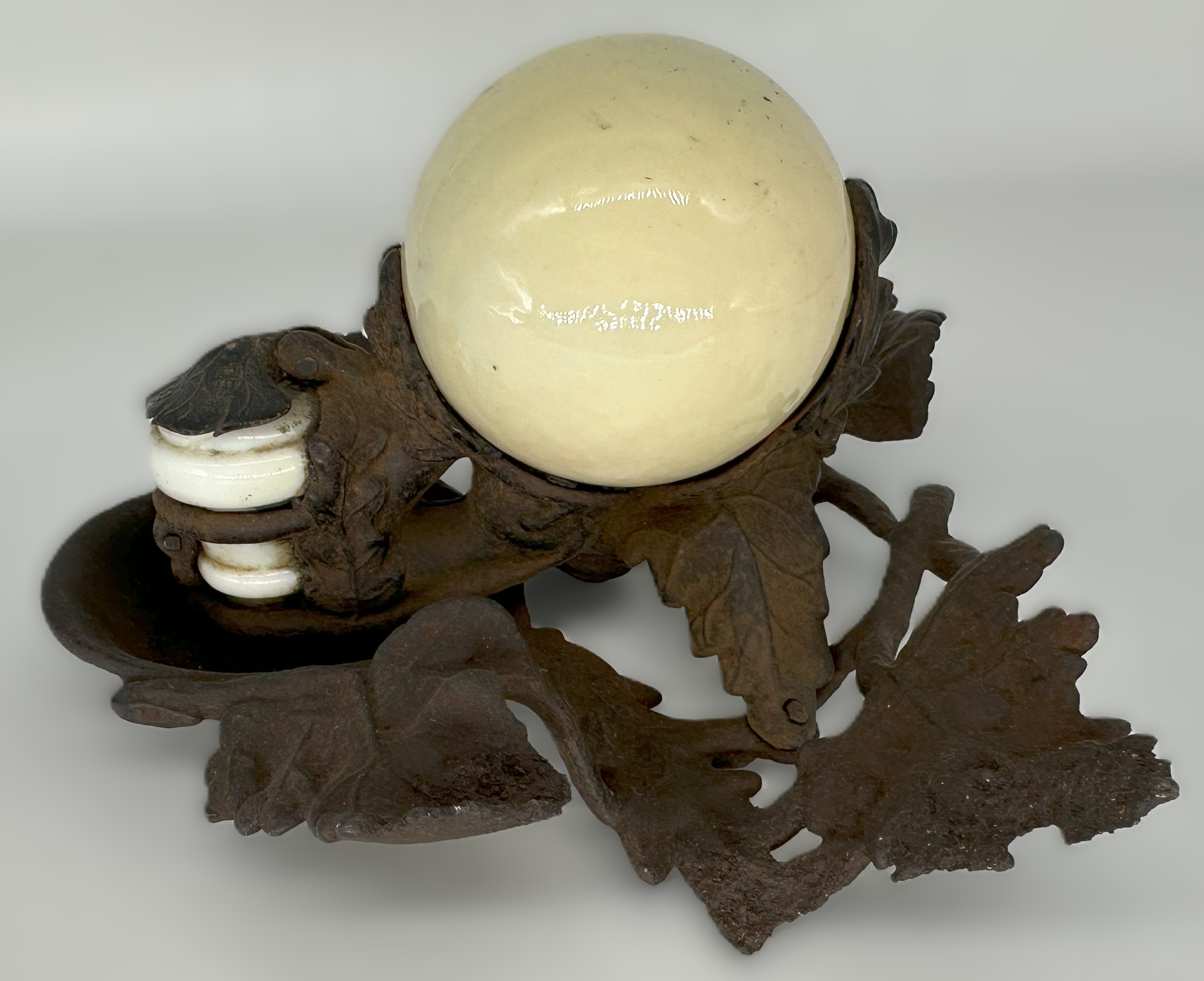
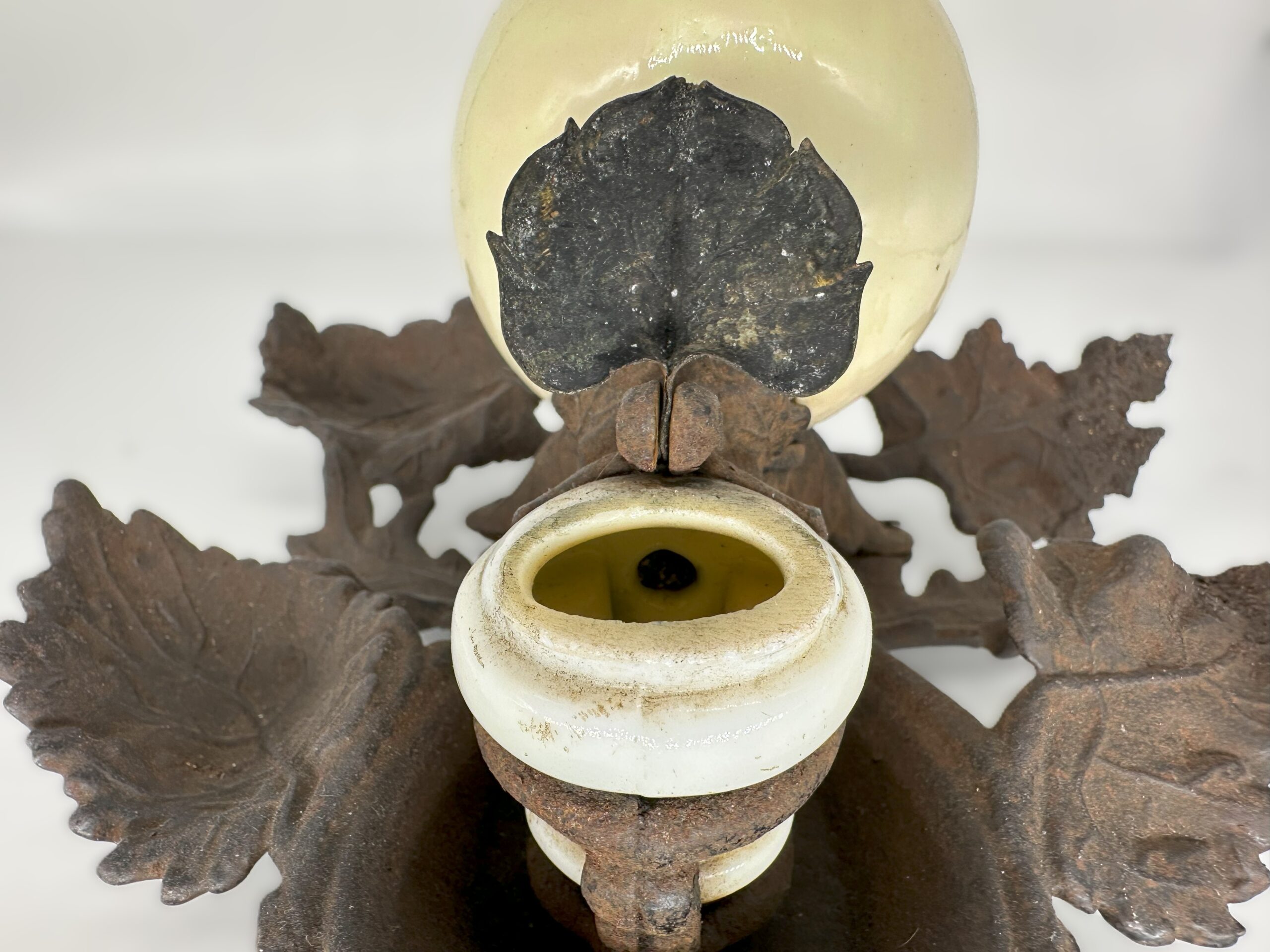
The glass piece is particularly complex. It is a single, molded unit featuring a large ink reservoir at the back and a smaller, shallow “font” or dish at the front. A glass appendage connects the two, allowing ink to flow from the reservoir into the font. The complexity of this single-piece glass molding, made using a “snap case” process, speaks to the manufacturing techniques of the time and would have made it a relatively expensive (and now scarce) item.
How the Inkstand Works (Based on Patent #13,902)
This inkstand is a nice example of a fountain inkwell, a category of inkwells designed to automatically replenish the ink level in the dipping font. The entire system is based on the principles of air pressure and a siphon. The ingenuity of this inkwell lies in its sealed design, which prevents air from entering the main reservoir to maintain a constant ink level. As the patent reads, there is “no opening for admission of air.”
- Filling: To fill the inkstand, the ink is poured into the front font using a specialized filler or pipette to transfer the ink from the font, up through the connecting glass channel, and into the main spherical reservoir. This allows the ink to be added without breaking the vacuum that keeps the system working properly.
- Function: Once filled, the ink flows through the connecting appendage into the small, front font. As a pen is dipped and ink is consumed, the ink level in the font drops.
- Automated Flow: When the ink level in the font falls below the opening of the connecting appendage, a small amount of air is drawn into the main reservoir. This release of vacuum allows a corresponding amount of fresh ink to flow from the reservoir into the font, bringing the ink level back up to a constant, ideal height.
This mechanism ensures a consistent, clean supply of ink for dipping the pen, while keeping the main supply sealed from air and dust. It addressed the common problems of ink evaporation and spillage. The invention, patented by Charles T. Close in 1855, was a technological advancement for the home and office of the era.
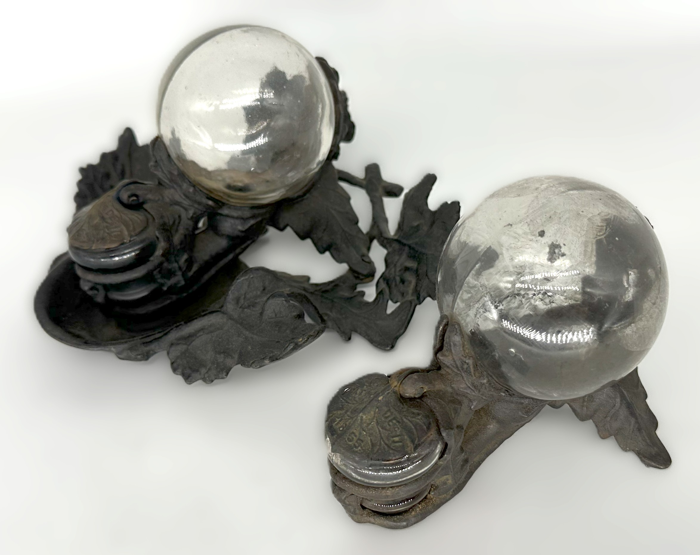
Four examples are pictured:
- One with a clear glass reservoir and frame with a leaf design.
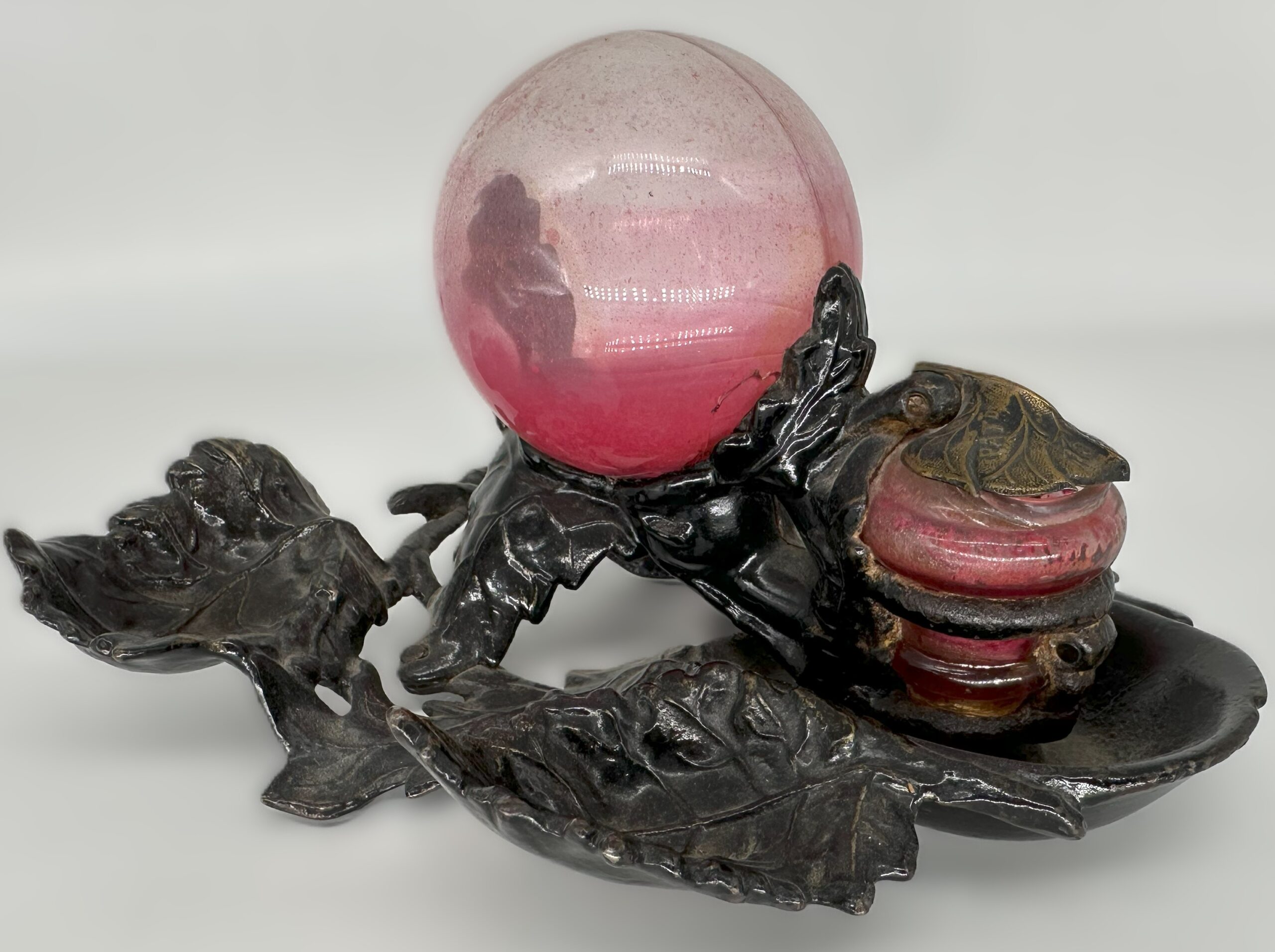
- One with the same design but stained with red ink.
- One with a milk glass reservoir.
- A smaller version with just the basic inkwell design without the frame.
Estimated value: $300
Content disclaimer. The information posted is the owner’s best knowledge and may not have been vetted by the SOIC. We welcome comments, corrections, and additions, working to make our website information comprehensive and accurate.
Join the Society of Inkwell Collectors (SOIC) – it’s free!
Founded in 1981 as a non-profit organization,
we are documenting inkwells (and accessories).
We’re here to help and inform!